Infrastructure Services
Some of the aspects to consider are, whether the underlying data centre infrastructure supports ToR resiliency, i.e. features like link bundling (bonds), BGP, support for anycast service, load balancer, firewall, Quality of Service.
As seen in previous sections, to deploy applications at scale, it will need certain capabilities to be supported from the infrastructure. This section will cover different options available, and their suitability.
ToR connectivity
This being one of the most frequent points of failure (considering the scale of deployment), there are different options available to connect the servers to the ToR. We are going to see them in detail below,
Single ToR
This is the simplest of all the options. Where a NIC of the server is connected to one ToR. The advantage of this approach is, there is a minimal number of switch ports used, allowing the DC fabric to support the rapid growth of server infrastructure (Note: Not only the ToR ports are used efficiently, but the upper switching layer in DC fabric as well, the port usage will be efficient). On the downside, the servers can be unreachable if there is an issue with the ToR, link or NIC. This will impact the stateful apps more, as the existing connections get abruptly disconnected.
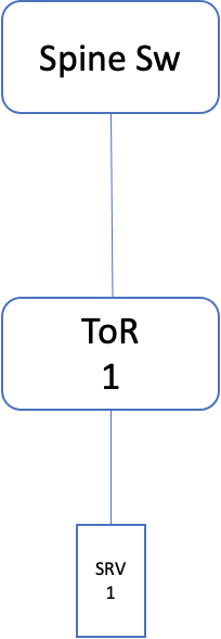
Fig 4: Single ToR design
Dual ToR
In this option, each server is connected to two ToR, of the same cabinet. This can be set up in active/passive mode, thereby providing resiliency during ToR/link/NIC failures. The resiliency can be achieved either in layer 2 or in layer 3.
Layer 2
In this case, both the links are bundled together as a bond on the server side (with one NIC taking the active role and the other being passive). On the switch side, these two links are made part of multi-chassis lag (similar to bonding, but spread across switches). The prerequisite here is, both the ToR should be part of the same layer 2 domain. The IP addresses are configured on the bond interface on the server and SVI on the switch side.
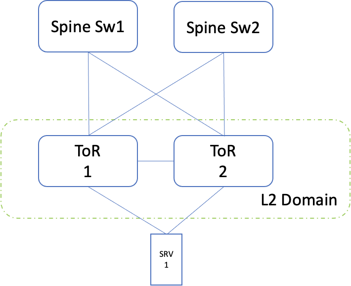
Note: In this, the ToR 2 role is only to provide resiliency.
Fig 5: Dual ToR layer 2 setup
Layer 3
In this case, both the links are configured as separate layer 3 interfaces. The resiliency is achieved by setting up a routing protocol (like BGP). Wherein one link is given higher preference over the other. In this case, the two ToR's can be set up independently, in layer 3 mode. The servers would need a virtual address, to which the services have to be bound.
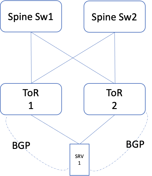
Note: In this, the ToR 2 role is only to provide resiliency.
Fig 6: Dual ToR layer 3 setup
Though the resiliency is better with dual ToR, the drawback is, the number of ports being used. As the access port in the ToR doubles up, the number of ports required in the Spine layer also doubles up, and this keeps cascading to higher layers.
| Type | Single ToR | Dual ToR (layer 2) | Dual ToR (layer 3) |
|---|---|---|---|
| Resiliency1 | No2 | Yes | Yes |
| Port usage | 1:1 | 1:2 | 1:2 |
| Cabling | Less | More | More |
| Cost of DC fabric | Low | High | High |
| ToR features required | Low | High | Medium |
1 Resiliency in terms of ToR/Link/NIC
2 As an alternative, resiliency can be addressed at the application layer.
Along with the above-mentioned ones, an application might need more capabilities out of the infrastructure to deploy at scale. Some of them are,
Anycast
As seen in the previous section, of deploying at scale, anycast is one of the means to have services distributed across cabinets and still have traffic flowing to each one of the servers. To achieve this, two things are required
-
Routing protocol between ToR and server (to announce the anycast address)
-
Support for ECMP (Equal Cost Multi-Path) load balancing in the infrastructure, to distribute the flows across the cabinets.
Load balancing
Similar to Anycast, another means to achieve load balancing across servers (host a particular app), is using load balancers. These could be implemented in different ways
-
Hardware load balancers: A LB device is placed inline of the traffic flow, and looks at the layer 3 and layer 4 information in an incoming packet. Then determine the set of real hosts, to which the connections are to be redirected. As covered in the Scale topic, these load balancers can be set up in two ways,
-
Single-arm mode: In this mode, the load balancer handles only the incoming requests to the VIP. The response from the server goes directly to the clients. There are two ways to implement this,
-
L2 DSR: Where the load balancer and the real servers remain in the same VLAN. Upon getting an incoming request, the load balancer identifies the real server to redirect the request and then modifies the destination mac address of that Ethernet frame. Upon processing this packet, the real server responds directly to the client.
-
L3 DSR: In this case, the load balancer and real servers need not be in the same VLAN (does away with layer 2 complexities like running STP, managing wider broadcast domain, etc). Upon incoming request, the load balancer redirects to the real server, by modifying the destination IP address of the packet. Along with this, the DSCP value of the packet is set to a predefined value (mapped for that VIP). Upon receipt of this packet, the real server uses the DSCP value to determine the loopback address (VIP address). The response again goes directly to the client.
-
-
Two arm mode: In this case, the load balancer is in line for incoming and outgoing traffic.
-
-
DNS based load balancer: Here the DNS servers keep a check of the health of the real servers and resolve the domain in such a way that the client can connect to different servers in that cluster. This part was explained in detail in the deployment at scale section.
-
IPVS based load balancing: This is another means, where an IPVS server presents itself as the service endpoint to the clients. Upon incoming request, the IPVS directs the request to the real servers. The IPVS can be set up to do health for the real servers.
NAT
Network Address Translation (NAT) will be required for hosts that need to connect to destinations on the Internet, but don't want to expose their configured NIC address. In this case, the address (of the internal server) is translated to a public address by a firewall. Few examples of this are proxy servers, mail servers, etc.
QoS
Quality of Service is a means to provide, differentiate treatment to few packets over others. These could provide priority in forwarding queues, or bandwidth reservations. In the data centre scenario, depending upon the bandwidth subscription ratio, the need for QoS varies,
-
1:1 bandwidth subscription ratio: In this case, the server to ToR connectivity (all servers in that cabinet) bandwidth should be equivalent to the ToR to Spine switch connectivity. Similarly for the upper layers as well. In this design, congestion on a link is not going to happen, as enough bandwidth will always be available. In this case, the only difference QoS can bring, it provides priority treatment for certain packets in the forwarding queue. Note: Packet buffering happens, when the packet moves between ports of different speeds, like 100Gbps, 10Gbps.
-
Oversubscribed network: In this case, not all layers maintain a bandwidth subscription ratio, for example, the ToR uplink may be of lower bandwidth, compared to ToR to Server bandwidth (This is sometimes referred to as oversubscription ratio). In this case, there is a possibility of congestion. Here QoS might be required, to give priority as well as bandwidth reservation, for certain types of traffic flows.